Products PRODUCTS
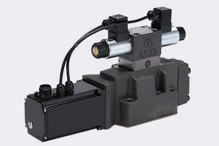
Extra Quick Response Type Proportional Directional Control Valves Pilot Operated
Products
Proportional Directional Control Va...

Extra Quick Response Type Proportional Directional Control Valves Pilot Operated
DPGKE 10/16/25/27/32/35 (with position control)
- Pilot operated 2-stage proportional directional valve with electrical position feedback of the main spool and integrated electroncics (OBE)
- The control of the size and direction of a flow
- Actuation via proportional solenoids
- For subplate mounting:
Porting pattern to ISO 4401(NS 10 to 35),
subplates to catalogue sheets, see pages 15 to 18 - Electrical position feedback
- Spring-centred main spool
- The pilot control is a single stage proportional directional control valve
- Main stage with closed loop positon control
- Integrated control electronics

- Pilot control valve type DPGKE-6-3C40-D24 (1st stage)
- The pilot control valve is a direct operated proportional valve.
- The control edge geometry was designed and optimised for use as a pilot control valve for the proportional directional valves type DPGKE.
- The proportional solenoids are pressure tight, oil-immersed DC solenoids with removable coil. They covert an electrical current proportionally into a mechanical force. An increase in the current strength causes an appropriately higher solenoid force. The set solenoid force remains constant over the entire control stroke.
- The pilot control valve basically consists of the housing (1), proportional solenoids (2 and 3), valve spool (4) and springs (5 and 6).
- In the de-energised condition both actuator ports are connected to the tank. If one of the two solenoids (2 or 3) is energised, then the solenoid force moves the valve spool (4) against the spring (5 or 6).
- Once the overlap area is overcome, the connection to tank of one of the two actuator ports is blocked and the connection pressure chamber is establised. There is flow from P to the control chamber of the main stage.

Valve Features
- The type DPGKE valves are 2-stage proportional directional control valves.
- They control the size and direction of a flow.
- The main stage is closed loop position controlled so that the spool position is also independent of flow forces at larger flows.
- The valve basically consists of the pilot control valve (1), housing (8), main spool (7), covers (5 and 6), centering spring (4), inductive position transducer (9) and the pressure reducing valve (3).
- If no input signal is being applied, then the main spool (7) is held in the centre position by the centering spring (4). The two control chambers in the covers (5 and 6) are connected via the valve spool (2) to the tank.
- The main spool (7) is connected to suitable control electronics via the inductive position transducer (9). the positional change of the main spool (7) as well as the alteration of the command value at the summation point of the amplifier produces a differential voltage.
- With the command value/actual value comparison a possible control deviation is recognised via the electronics and an electrical current is applied to the proportional solenoid of the pilot valve (1).
- The current induces, within the solenoid, a force which is passed onto the solenoid pin which in turn actuates the control spool. The flow which is provided via the control cross-sections causes the main spool to move.
- The main spool (7) with the attached core of the inductive position transducer (9) is moved until the actual value is equal to the command value. In the closed loop controlled condition the main spool (7) is force balanced and is held in this closed loop controlled position.
- Spool stroke and control opening change in proportional to the command value.
- The control electronics are integrated into the valve. By matching the valve and electronics the spread of the series units is kept low.
- Prevent the tank lines from emptying; with appropriate installation conditions, a back pressure valve is to be installed (back pressure approx. 2 bar).

- The 2nd stage basically comprises of components fromour proportional valves.
- The zero point adjustment at the „main stage zero point“ is factory pre-set and can, via a potentiometer in the control electronics, be adjusted within a range of ±30 % of the zero stroke. The integrated control electronics can be accessed by removing a plug in the housing.
- If the pilot control valve or the control electronics are exchanged then these have to be recalibrated. All calibrations must only be carried out by trained personnel.


